Robotic Metrology for AM post-processing
The Metrology Project is my main research project at CERLAB. The idea is to develop an automated testing pipeline for additively manufactured parts. Metal based 3D printing allows us to print functional parts with a complex topology with ease. But when those parts are to be used in high accuracy situations it is important that they are free of any defects which may cause failure. Due to the high volume of parts, it is not always feasible to go around manually inspecting each part which is printed. Additionally, the complex geometries make it more difficult to take precise measurements of the parts.
So how do we do it? The solution, theoretically is really simple. Mount a very good sensor at the end of the arm. Use that arm to capture observation of the object we are interested in. Stitch all the observations together and we have a reconstruction of the printed part. Now we can compare it against the actual part file and analyze for inconsistencies.
Hardware
In a broad classification, we have four major parts in our hardware system. First the specimen which we are scanning, the sensor which we are using to perform the scans, a 6 DOF robot arm which helps move the sensor around and orient it, and lastly a turntable which provides an additional redundant DOF to the system. Using a combination of these 6+1 DOFs we can find solutions to the viewpoint planning problem.

Currently we use two categories of sensors to capture the scans. In the first category, we have a laser profiler that capture measurements in a single dimension with a high degree of accuracy. We use this one for specific areas where the accuracy requirement is high. On the other hand, we also use a structured light sensor which provides a faster scanning time at a decent accuracy. Both have their pros and cons but balance each other out.

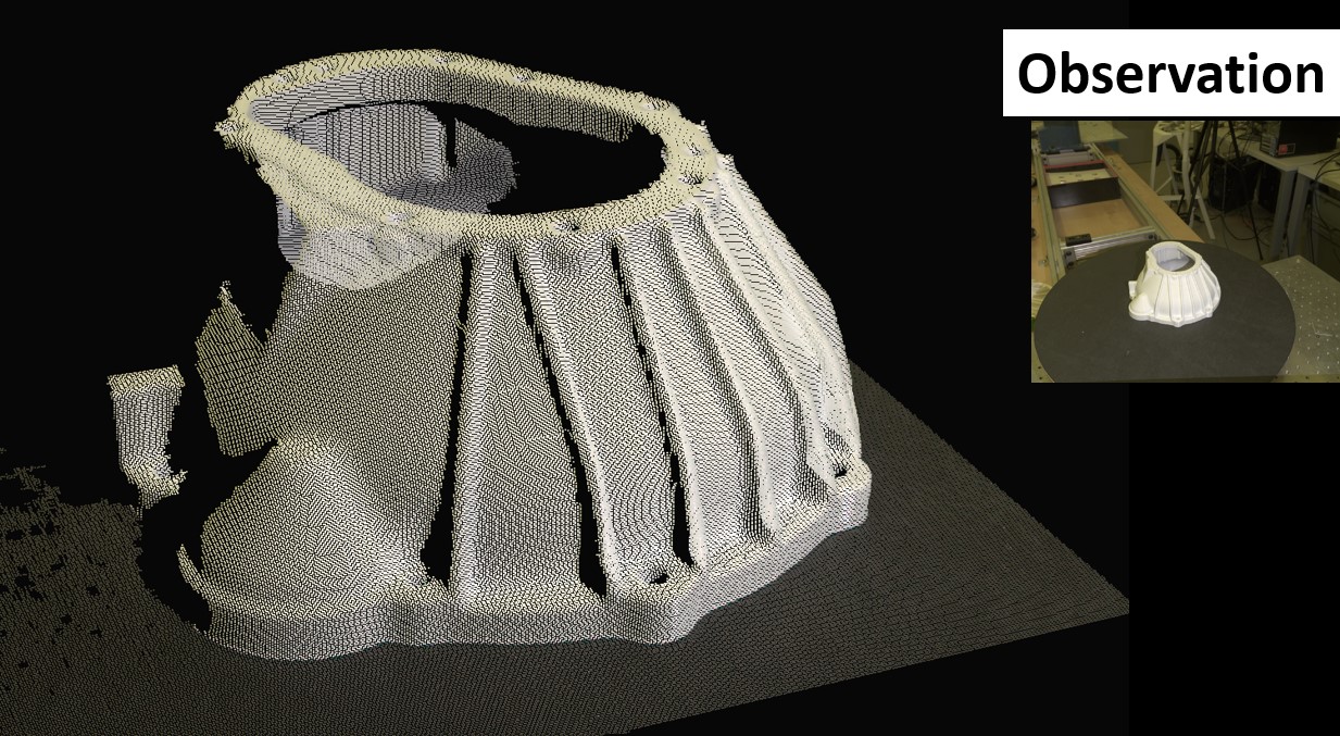
The below image shows a sample of what an observation from our structured light sensor gives us from one viewpoint. On the top right corner is what the inbuilt camera in the sensor sees during the measurement. We get a very dense point cloud of the object placed in our area of interest on the turntable, with the sensor capable of capturing 5000 point measurements per square centimeter. Combine one such observation with the rest of the set allows a very dense reconstruction of the object.

Software Pipeline
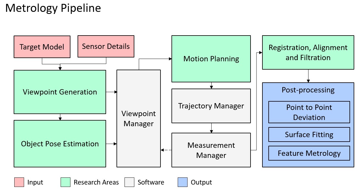
Our current pipeline expects the base models of the specimen and the sensor details to start working. The first module solves for the viewpoint planning problem and provides a minimal set of feasible viewpoints which allows for full surface coverage of the specimen. An object pose estimator isolates and corrects the viewpoints based on the current positioning of the specimen on the turntable. Our motion planning module solves the inverse kinematics for the entire 7 degree chain and the manages the hardware control of our setup. Once all the observations have been captured, we segment out the specimen and register them into a single reconstructed point cloud. This can then be passed on for postprocessing.

